In the previous tutorials, we have seen what is capacitance and charge?. In this tutorial we are going to learn how to read the capacitor value?. For some applications, it is necessary to know the tolerance and voltage values of the capacitor along with the capacitance. All these parameters are represented on the body of the capacitor.
Different types of capacitors have different ways of representing the capacitance values . Capacitors like electrolytic capacitors, non- polarised capacitors, large ac oil filled paper capacitors have capacitance and voltage, tolerance values written on its body using numbers and letters.Some capacitors have values represented using color code. Let us see how to read capacitance value in these two methods.
How to read capacitor value written on capacitors??
Let us see how to read the capacitor values with numbers and alphabets. Along with the capacitance other values like tolerance and voltage were written on the capacitor itself if there is enough space. But for small capacitors like ceramic capacitors , as the space is not enough , capacitor values are represented using shorthand notation.
Reading capacitor values on Large capacitor(cylindrical capacitors)
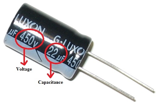
For large capacitors, generally capacitor value is written on the side of the capacitor.
- The above figure shows a 22 micro farad capacitor .Capacitance value is expressed in Farads (F or FD).
- Here are the units used for representing capacitor value .Micro farad (uf,µf,mF (or) MF) , Nano farad ( nF ), Pico farad(pF).
| uF(or)MF(or)mF | Microfarad | 10-6 |
| nF | Nanofarad | 10-9 |
| pF(or)mmF(or)uuF | Picofarad | 10-12 |
- Voltage rating on the capacitor indicates the maximum value voltage that capacitor can handle.Voltage rating on the capacitor is indicated by V, VDC, and VDCW.
- VAC represents that capacitor is designed for AC circuit.
- It is to be noted that DC rating capacitors should not be used for AC unless you have proper knowledge to use that capacitor. Some capacitors have voltages represented in codes instead of value.
- Tolerance value is indicated using % symbol before the number. Tolerance value represents the variation of capacitance value .
Reading the values of small capacitors(ceramic capacitors)
Ceramic capacitors have very small area to print the value of capacitance. So capacitance on these capacitors is represented using short hand notation. Let us see how to calculate these values. Generally capacitance of ceramic, tantalum ,film capacitors is expressed in Pico Farad.
Step 1: If the capacitor has two numerical values.
- If the notation on the capacitor has 2 digits and a letter (like 22M) ,then it has capacitance value of 22.
Some capacitors have letters in the second position and numerical value in first position.
Ex: 5R2 = 5.2PF. - In place of R if the letters like p, n, u are present then they represent units of capacitance.
Ex: 4n1 = 4.1nF, p45=0.45pF
Step 2:Some of them have three numerical values.
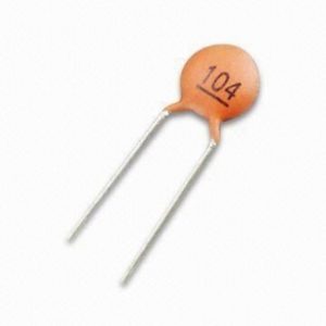
- Capacitor shown above has notation 104 on it.
- Capacitance is calculated as 10x 104 = 105pf = 0.1uf
- If the third digit is between 0 to 6 follow the above procedure.
- If it is 8 multiply it by using 0.01.for example 158 =15×0.01 = 0.15pF
- If it is 9 multiply it by using 0.1.For example 159 =15×0.1 =1.5pF
Tolerance
The tolerance value for these capacitors is represented using single letter.Each letter has a value.
| A | ±0.05 pF |
| B | ±0.1 pF |
| C | ±0.25 pF |
| D | ±0.5 pF |
| E | ±0.5% |
| F | ±1% |
| G | ±2% |
| H | ±3% |
| J | ±5 % |
| K | ±10% |
| L | ±15% |
| M | ±20% |
| N | ±30% |
| P | –0%, + 100% |
| S | –20%, + 50% |
| W | –0%, + 200% |
| X | –20%, + 40% |
| Z | –20%, + 80% |
Capacitance value Calculator
- Color coding of capacitors is an age old technique. But some of these capacitors are still in use today. So let us see how to calculate the value of capacitance and voltage rating if they are represented using color coding.
- Generally color codes are indicated using Dots or Bands. For Mica capacitors color coding is shown in Dots while for tubular capacitors it may be shown using bands. The number of dots or bands on a capacitor may vary from one another .
Below two tables shows the values of colors given on the capacitors.
Capacitance Color Code Table
| Band | Digit | Digit | Multiplier | Tolerance | Tolerance |
| Color | A | B | D | (T) > 10pf | (T) < 10pf |
| Black | A | 0 | x1 | ±20% | ±2.0pF |
| Brown | 1 | 1 | x10 | ±1% | ±0.1pF |
| Red | 2 | 2 | x100 | ±2% | ±0.25pF |
| Orange | 3 | 3 | x1000 | ±3% | |
| Yellow | 4 | 4 | x10,000 | ±4% | |
| Green | 5 | 5 | x100,000 | ±5% | ±0.5pF |
| Blue | 6 | 6 | x1,000,000 | ||
| Violet | 7 | 7 | |||
| Grey | 8 | 8 | x0.01 | +80 ,-20% | |
| White | 9 | 9 | x0.1 | ±10% | ±1.0pF |
| Gold | x0.1 | ±5% | |||
| Silver | x0.01 | ±10% |
Capacitor Voltage Color Code
| Colour | Type | TypeK | TypeL | TypeM | TypeN |
| Black | 4 | 100 | – | 10 | 10 |
| Brown | 6 | 200 | 100 | 1.6 | – |
| Red | 10 | 300 | 250 | 4 | 35 |
| Orange | 15 | 400 | – | 40 | – |
| Yellow | 20 | 500 | 400 | 6.3 | 6 |
| Green | 25 | 600 | 16 | 15 | |
| Blue | 35 | 700 | 630 | – | 20 |
| Violet | 50 | 800 | – | – | – |
| Grey | – | 900 | – | 25 | 25 |
| White | 3 | 1000 | – | 2.5 | 3 |
| Gold | – | 2000 | – | – | – |
| Silver | – | – | – | – | – |
Let us see an example of ceramic or disc capacitor for calculating the color code on it.
Disc & Ceramic Capacitor

Figure 2. Disc capacitors with colour codes
These colour codes are used from many years for non-polarized capacitors like disc and ceramic capacitors. But it is difficult to identify the values in the case of old capacitors. So these old capacitors are now replaced with new numbers.


